
The resources to write a rasterizer from scratch exist, but they are scattered everywhere: Stack Overflow answers, research papers, technical articles, repositories. AmberGL, my software renderer, was built by putting those pieces together one by one.
I'm not a mathematician, far from it. I didn't invent any of this, and I had to rack my brain for a long time to take it all in and understand it. So every chapter starts from working code, and only brings in the math when it's really needed.
This series is not me playing the teacher. The goal is simply to gather all that knowledge in one place, a place I can come back to myself: my experience writing AmberGL, what I keep learning while I implement software renderers, and everything I found along the way. If you want to see the code running, it's all in the repository. Just keep in mind it's a learning project, not the ultimate reference: I'm already on my third software renderer in my free time, and each one fixes things the previous one got wrong.
The problem
After the vertex shader, the clipping and the viewport transform, a triangle is just three points on the screen. The rasterizer has to answer one question: which pixels does this triangle cover?
A pixel is a small square, but the test is done on a single point of that square: its center. If the center is inside the triangle, the pixel is drawn. Otherwise it's skipped, even if the triangle covers a part of it.
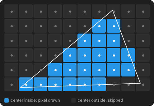
In AmberGL, the pixel centers are handled once, in the viewport transform. The - 0.5f shifts the vertices by half a pixel, so the integer position (x, y) tested later lands on the center of the pixel instead of its corner.
glm::vec2 ComputeRasterSpaceCoordinate(glm::vec2 p_vertexNormalizedPosition)
{
	p_vertexNormalizedPosition.x = RenderContext.Viewport.X
		+ p_vertexNormalizedPosition.x * RenderContext.Viewport.Width - 0.5f;

	p_vertexNormalizedPosition.y = RenderContext.Viewport.Y
		+ p_vertexNormalizedPosition.y * RenderContext.Viewport.Height - 0.5f;

	return p_vertexNormalizedPosition;
}There are two big families of algorithms to find the covered pixels: scanline and bounding box with barycentric coordinates. AmberGL uses the second one, but you can't understand why without knowing the first one.
Scanline
Scanline is the approach Michael Abrash describes as "often used by scalar software rasterizers": code that handles one pixel after another. The idea: a triangle is drawn row by row, from top to bottom. For each row, you only need two numbers, where the triangle starts and where it ends. Then you fill everything in between.
The trick is that the left and right borders of a row are always given by two edges of the triangle. To keep it simple, the triangle is cut in two at the height of its middle vertex: a top half whose bottom side is flat, and a bottom half whose top side is flat. Each half has exactly one left edge and one right edge.
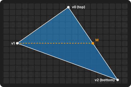
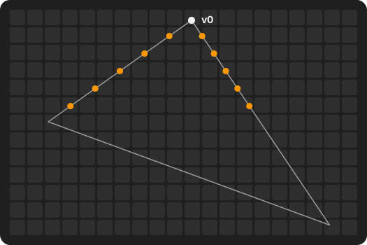
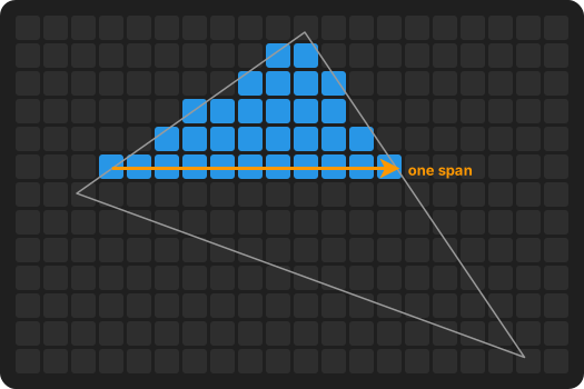
Walking down an edge is cheap. Along a straight line, each time you go down one row, x always moves by the same amount: dx / dy, the inverse of the slope. So each row only costs one addition per edge. In pseudo-code:
// Sort the three vertices by y: v0 on top, v2 at the bottom.
// M is the point of the long edge v0 -> v2 at the height of v1.
M.y = v1.y
M.x = v0.x + (v2.x - v0.x) * (v1.y - v0.y) / (v2.y - v0.y)

FillFlatBottom(v0, v1, M)   // top half
FillFlatTop(v1, M, v2)      // bottom half

FillFlatBottom(top, left, right):
	slopeLeft  = (left.x  - top.x) / (left.y  - top.y)
	slopeRight = (right.x - top.x) / (right.y - top.y)
	xLeft  = top.x
	xRight = top.x

	for y from top.y to left.y:
		fill the pixels from xLeft to xRight on row y
		xLeft  += slopeLeft
		xRight += slopeRight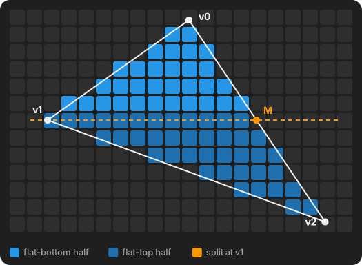
That's the strength of scanline: it only visits the pixels that are inside. Its weaknesses come from the same place. Everything depends on the previous row, the vertices have to be sorted, the triangle has to be split, and the flat cases need their own code path. And to know the color or the UV of a pixel, you first interpolate along the edges, then again along the row.
Bounding box and edge functions
The other approach flips the question. Instead of computing where the triangle is on each row, you take every pixel that could be in the triangle, and you ask each one: are you inside?
The bounding box
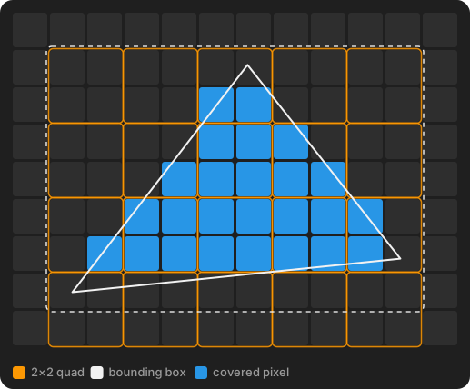
The candidates are the pixels of the smallest rectangle around the triangle: its bounding box. In AmberGL, it's computed once when the triangle is built, from the min and max of the three vertices.
Triangle::Triangle(const glm::vec2& p_vertex0, const glm::vec2& p_vertex1, const glm::vec2& p_vertex2)
	: Vertices{ p_vertex0, p_vertex1, p_vertex2 }
{
	PreComputeBarycentricCoordinates();

	const float minX = std::min({ p_vertex0.x, p_vertex1.x, p_vertex2.x });
	const float maxX = std::max({ p_vertex0.x, p_vertex1.x, p_vertex2.x });

	const float minY = std::min({ p_vertex0.y, p_vertex1.y, p_vertex2.y });
	const float maxY = std::max({ p_vertex0.y, p_vertex1.y, p_vertex2.y });

	BoundingBox2D.Min.x = static_cast<int32_t>(std::floor(minX));
	BoundingBox2D.Min.y = static_cast<int32_t>(std::floor(minY));
	BoundingBox2D.Max.x = static_cast<int32_t>(std::ceil(maxX));
	BoundingBox2D.Max.y = static_cast<int32_t>(std::ceil(maxY));
}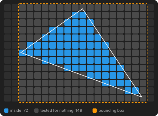
Yes, a lot of pixels are tested for nothing. A triangle never covers more than half of its bounding box, and a thin diagonal triangle covers almost none of it. Keep that in mind, we'll come back to why it's still worth it.
Which side of an edge?
Now the question: is a pixel inside the triangle? It starts with a simpler one: on which side of a line is a point? That's what the edge function answers. This is the one in AmberGL:
float Triangle::ComputeEdge(const glm::vec2& p_vertex0, const glm::vec2& p_vertex1, const glm::vec2& p_vertex2) const
{
	return (p_vertex1.x - p_vertex0.x) * (p_vertex2.y - p_vertex0.y)
	     - (p_vertex1.y - p_vertex0.y) * (p_vertex2.x - p_vertex0.x);
}
It's a 2D cross product. Give it the two points of an edge, a and b, and a third point p. The result is positive on one side of the line, negative on the other side, and zero exactly on the line.
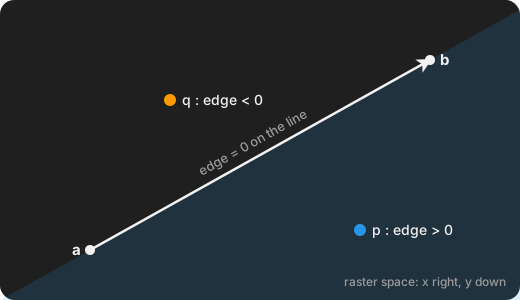
A triangle has three edges. Walk around them in order, v0 → v1, v1 → v2, v2 → v0: a point is inside the triangle when it's on the same side of all three. If one of them disagrees, the point is outside.
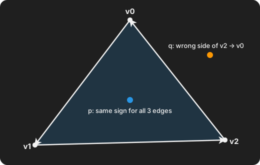
The edge function gives one more thing for free. Its value is twice the area of the triangle formed by a, b and p, with a sign. Call it on the three vertices of the triangle itself, and you get the area of the whole triangle. The sign tells in which order the vertices turn on screen, clockwise or counterclockwise. AmberGL uses exactly that to drop the back faces before rasterizing anything:
Triangle triangle(vertexRasterPosition0, vertexRasterPosition1, vertexRasterPosition2);

float area = triangle.ComputeArea(); // ComputeEdge(Vertices[0], Vertices[1], Vertices[2])

if (RenderContext.State & AGL_CULL_FACE)
{
	if ((RenderContext.CullFace == AGL_BACK && area > 0.0f)
		|| (RenderContext.CullFace == AGL_FRONT && area < 0.0f)
		|| RenderContext.CullFace == AGL_FRONT_AND_BACK)
		return;
}Barycentric coordinates
Back to the areas. Take a point p inside the triangle and connect it to the three vertices. It cuts the triangle into three smaller triangles. Divide the area of each small triangle by the area of the whole triangle, and you get three numbers, w0, w1 and w2: the barycentric coordinates of p.
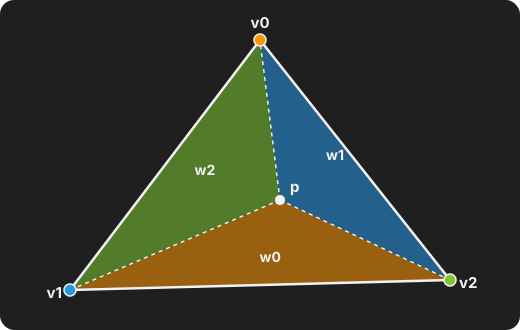
w0 is the orange one, opposite to v0.These three weights are all you need:
- They always add up to 1.
- The closer
pis to a vertex, the bigger its weight. On the vertex itself, its weight is 1 and the two others are 0. - If
pis outside the triangle, at least one weight is negative. That's the same test as the edge functions, just divided by the area.
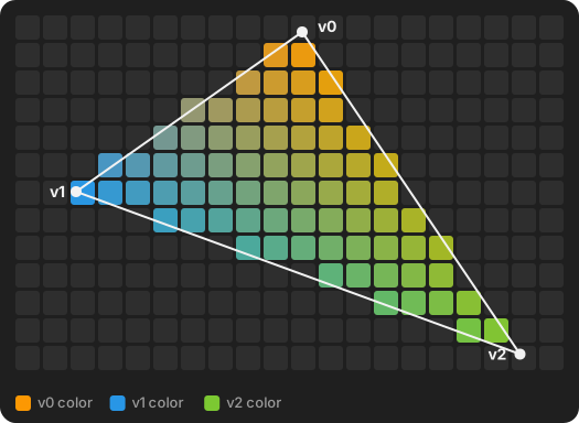
And the best part: the same three weights blend anything stored on the vertices. A color, a UV, a normal, a depth: multiply each vertex value by its weight and add them up.
How AmberGL computes them
You could compute the three weights with three edge functions and a division by the area. AmberGL does it a bit differently, with an adaptation of the method from Christer Ericson's book Real-Time Collision Detection. The idea is the same: p is described as v0 plus a part u of the edge v0 → v1 plus a part v of the edge v0 → v2. Two unknowns, two equations (one for x, one for y), solved with dot products.
What I like about it: everything that only depends on the triangle is computed once, when the triangle is built. Per pixel, it's just two dot products and a few multiplications.
// Christer Ericson's Real-Time Collision Detection book adaptation.
void Triangle::PreComputeBarycentricCoordinates()
{
	m_vertex0 = glm::vec2(Vertices[2].x - Vertices[0].x, Vertices[2].y - Vertices[0].y);
	m_vertex1 = glm::vec2(Vertices[1].x - Vertices[0].x, Vertices[1].y - Vertices[0].y);
	m_d00 = m_vertex0.x * m_vertex0.x + m_vertex0.y * m_vertex0.y;
	m_d01 = m_vertex0.x * m_vertex1.x + m_vertex0.y * m_vertex1.y;
	m_d11 = m_vertex1.x * m_vertex1.x + m_vertex1.y * m_vertex1.y;
	m_denom = 1.0f / (m_d00 * m_d11 - m_d01 * m_d01);
}

glm::vec3 Triangle::GetBarycentricCoordinates(const glm::vec2& p_vertex) const
{
	const float x = p_vertex.x - Vertices[0].x;
	const float y = p_vertex.y - Vertices[0].y;

	const float d02 = m_vertex0.x * x + m_vertex0.y * y;
	const float d12 = m_vertex1.x * x + m_vertex1.y * y;

	const float u = (m_d00 * d12 - m_d01 * d02) * m_denom;
	const float v = (m_d11 * d02 - m_d01 * d12) * m_denom;

	return glm::vec3(1.0f - u - v, u, v); // weights of v0, v1, v2
}The other way: straight from the edge functions
Ericson's method comes from collision detection, where you need the barycentric coordinates of any point against a triangle. A rasterizer has a more specific job, and there is a more direct way: the three edge functions are the small areas of the picture above, doubled. Divide them by the doubled area of the whole triangle and you have the weights.
// Once per triangle
const float invArea = 1.0f / ComputeEdge(v0, v1, v2);

// Per pixel
const float edge01 = ComputeEdge(v0, v1, p);
const float edge12 = ComputeEdge(v1, v2, p);
const float edge20 = ComputeEdge(v2, v0, p);

if (edge01 < 0.0f || edge12 < 0.0f || edge20 < 0.0f)
	continue; // outside

const float w0 = edge12 * invArea; // the edge in front of v0
const float w1 = edge20 * invArea; // the edge in front of v1
const float w2 = 1.0f - w0 - w1;
Both give the same weights. So why bother? Because the inside test and the weights now come from the same three numbers, and each number belongs to one edge. That opens the door to everything in the next section: exact integer math, a clean rule for shared edges, and pixels that cost a few additions. Ericson's version gives the same weights, but its dot products and float division don't map as directly onto the integer tricks below.
One condition: this code expects a positive area, so that "inside" always means "the three values are positive". We'll get there in the last part of this chapter.
Putting it together
Here is the core of the loop in AmberGL, cleaned up as an example: the parts about derivatives, depth test, stencil and MSAA are cut, they get their own chapters. It walks the bounding box, gets the weights of each pixel, rejects the pixel if one weight is negative, and reuses the same weights to get the depth.
for (uint32_t y = yMin; y < yMax; y += 2)
{
	for (uint32_t x = xMin; x < xMax; x += 2)
	{
		for (int dy = 0; dy < 2; dy++)
		{
			for (int dx = 0; dx < 2; dx++)
			{
				uint32_t px = x + dx;
				uint32_t py = y + dy;

				glm::vec3 bary = p_triangle.GetBarycentricCoordinates({ float(px), float(py) });

				// [...] interpolation used for the texture derivatives

				if (px >= xMax || py >= yMax)
					continue;

				// x and y are the weights of v0 and v1.
				// x + y > 1 means the weight of v2 is negative.
				if (bary.x < 0.0f || bary.y < 0.0f || bary.x + bary.y > 1.0f)
					continue;

				float depth = p_transformedVertices[0].z * bary.x
				            + p_transformedVertices[1].z * bary.y
				            + p_transformedVertices[2].z * bary.z;

				// [...] depth test, stencil test, fragment shader
			}
		}
	}
}
You may have noticed that the loop doesn't go pixel by pixel, but by blocks of 2×2 pixels, called quads. The blocks start at the corner of the bounding box, so the last ones can go past it: the extra pixels are still used for the texture derivatives, then skipped by px >= xMax || py >= yMax. Why quads? Because comparing a pixel with its neighbors is how the renderer knows which mipmap level to sample. That's for the textures chapter.
Going further: exact and cheap
The loop above works, and AmberGL renders with it. But it computes everything in floats, from scratch, for every pixel. Here are the techniques that make the edge functions exact and cheap.
Every triangle turns the same way
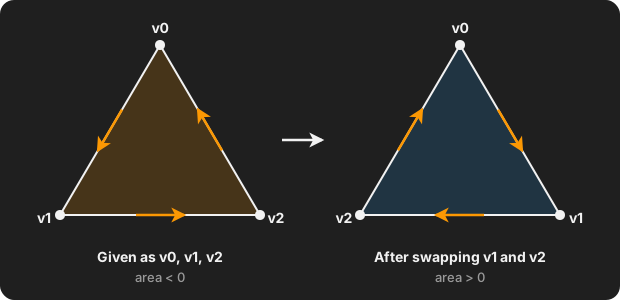
The sign of the area depends on the order of the vertices. Instead of handling both cases everywhere, the setup swaps two vertices when the area is negative. After that, every triangle has a positive area, and "inside" always means "the three edge values are positive or zero".
const float area = (screen1.x - screen0.x) * (screen2.y - screen0.y)
                 - (screen1.y - screen0.y) * (screen2.x - screen0.x);

if (std::abs(area) < 0.5f)
	return false; // smaller than a quarter of a pixel: dropped

// [...] face culling, with the sign of the area

if (area < 0.0f)
{
	std::swap(screen1, screen2);
	// the depth, 1/w and varyings of v1 and v2 are swapped too
}
The culling happens before the swap, while the sign still tells which side of the triangle faces the camera. Remember that area is twice the real area, so 0.5f means a quarter of a pixel. These tiny triangles are dropped early, which also keeps the 1 / area away from a division by zero.
With a positive area, and once the edge values are integers (that's the next part), the inside test becomes one line:
if ((edge01 | edge12 | edge20) < 0)
	return false; // outside
On integers, a negative number has its highest bit set. OR the three values together, and that bit survives if at least one of them is negative. One test instead of three.
Fixed point and subpixel precision
Two triangles that share an edge compute it each on their own, from their own vertices. With floats, the rounding can come out slightly different on each side. A pixel center right on that edge can then be drawn by both triangles, or by none, and you get holes or double pixels on the seams.
The fix is to stop using floats there. The vertex positions are snapped to a fine grid of 256 steps per pixel and stored as integers. From there, the edge functions are exact: the same numbers in, the same result out, on both sides of the edge.
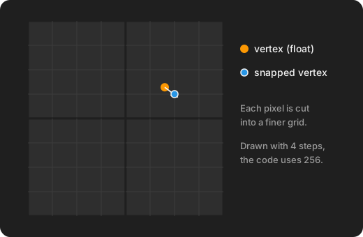
static constexpr int32_t SUBPIXEL_SHIFT = 8;
static constexpr int32_t SUBPIXEL_SCALE = 1 << SUBPIXEL_SHIFT; // 256 steps per pixel

static int32_t FloatToFixedPoint(float p_value)
{
	return static_cast<int32_t>(std::floor(p_value * SUBPIXEL_SCALE + 0.5f));
}

int64_t ComputeEdge(const Edge& p_edge, int32_t p_x, int32_t p_y) const
{
	// Two fixed-point numbers multiplied together can overflow 32 bits
	int64_t value = static_cast<int64_t>(p_edge.DeltaX) * (p_y - p_edge.OriginY)
	              - static_cast<int64_t>(p_edge.DeltaY) * (p_x - p_edge.OriginX);

	return (value + p_edge.FillBias) >> SUBPIXEL_SHIFT;
}
The pixel center becomes (x << 8) + 128: the pixel position in fixed point, plus half a pixel. Ignore FillBias for now, it's the next part.
GPUs do the same. As Fabian Giesen puts it in Triangle rasterization in practice, the standard in DX11-compliant GPUs is 8 bits of sub-pixel precision, coordinates in 1/256ths of a pixel. That's exactly the SUBPIXEL_SHIFT = 8 above.
The top-left rule
Exact math gives exact zeros. When a pixel center falls exactly on an edge, its edge value is 0. If that edge is shared, the two triangles both see a 0, and both draw the pixel. With blending, that pixel is blended twice and the seam shows.
The top-left rule decides who owns it. A triangle keeps the pixels on its top edge (a flat edge with the triangle below it) and on its left edges. It drops the pixels on its other edges. Two triangles that share an edge are on opposite sides of it, so exactly one of them owns it.
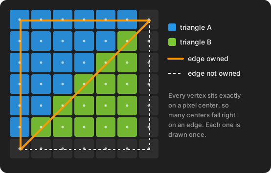
With the setup above (y going down, every triangle turned to a positive area), the vertices go around clockwise on screen. A left edge goes up, a top edge goes right:
static bool IsTopOrLeftEdge(int32_t p_deltaX, int32_t p_deltaY)
{
	return p_deltaY < 0 || (p_deltaY == 0 && p_deltaX > 0);
}

// Once per edge, in the triangle setup
edge.FillBias = IsTopOrLeftEdge(edge.DeltaX, edge.DeltaY) ? 0 : -1;
And here is the trick behind FillBias: on an edge the triangle doesn't own, the value gets -1 before the shift. An exact 0 becomes -1, negative, so the pixel is rejected. Any value above 0 stays positive or zero after the shift, so nothing else changes. No extra branch in the loop.
AmberGL doesn't have this rule. Its test accepts a weight equal to 0, so a pixel center exactly on a shared edge is drawn by both triangles.
Stepping the edge functions
Look at the edge function again: deltaX * (y - originY) - deltaY * (x - originX). Move one pixel to the right, and the value changes by -deltaY. Move one row down, and it changes by +deltaX. Always the same amounts, wherever you are.
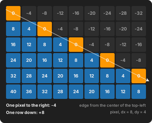
So there is no need to compute it from scratch for every pixel. Compute the three values once at the corner of the bounding box, then add:
// Edge values at the center of the first pixel of the box
int32_t row01 = ComputeEdge(edge01, minX, minY);
int32_t row12 = ComputeEdge(edge12, minX, minY);
int32_t row20 = ComputeEdge(edge20, minX, minY);

for (int32_t y = minY; y <= maxY; ++y)
{
	int32_t e01 = row01;
	int32_t e12 = row12;
	int32_t e20 = row20;

	for (int32_t x = minX; x <= maxX; ++x)
	{
		if ((e01 | e12 | e20) >= 0)
		{
			// inside: weights, depth test, fragment shader...
		}

		e01 -= edge01.DeltaY; // one pixel to the right
		e12 -= edge12.DeltaY;
		e20 -= edge20.DeltaY;
	}

	row01 += edge01.DeltaX; // one row down
	row12 += edge12.DeltaX;
	row20 += edge20.DeltaX;
}
Since the steps are whole numbers, the result is exactly the same as computing each pixel directly. It's the same idea as the dx / dy of scanline, a constant added at each step, with one big difference: any pixel can still be computed directly when needed. A tile can start anywhere, without walking from the top of the triangle.
Testing whole blocks first
Stepping makes each pixel cheap, but the bounding box still tests a lot of pixels for nothing. The next idea is to stop asking pixel by pixel, and ask block by block first. Michael Abrash describes it in Rasterization on Larrabee, with the names trivial reject and trivial accept.
The bounding box is cut into blocks, here 4×4 pixels. Since the edge function is linear, its smallest and largest values over a block are always on its corners. So the four corners are enough to know where the whole block stands:
- Trivial reject: for one of the edges, even the best corner is outside. The whole block is outside, its pixels are skipped without testing a single one.
- Trivial accept: for all three edges, even the worst corner is inside. The whole block is inside, its pixels are drawn without testing them one by one.
- Otherwise, the block touches an edge of the triangle, and only then each of its pixels is tested.
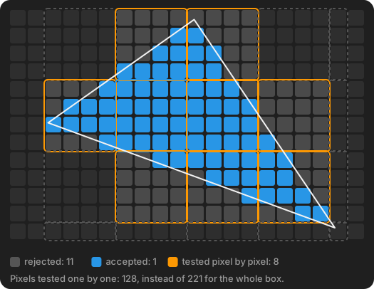
// Example: one edge against one block of B×B pixels, with the stepping values from above.
// e is the edge value at the center of the top-left pixel of the block.
const int32_t c00 = e;
const int32_t c10 = e - (B - 1) * edge.DeltaY; // top-right
const int32_t c01 = e + (B - 1) * edge.DeltaX; // bottom-left
const int32_t c11 = c10 + (B - 1) * edge.DeltaX; // bottom-right

const int32_t best  = std::max({ c00, c10, c01, c11 });
const int32_t worst = std::min({ c00, c10, c01, c11 });

if (best < 0)
	// trivial reject: the whole block is outside this edge

if (worst >= 0)
	// the whole block is inside this edge (trivial accept if true for the 3 edges)
It pays off on big triangles, where most blocks are either fully outside or fully inside. On small triangles that cover a few pixels, the block test is mostly extra work. Neither AmberGL nor my other renderers do it yet.
Scanline vs bounding box
| Scanline | Bounding box + barycentric | |
|---|---|---|
| Pixels visited | Only the covered ones | The whole bounding box |
| Setup | Sort, split, special cases for flat triangles | Min and max of three points |
| Interpolation | Along the edges, then along each row | Same three weights for everything |
| Dependency | Each row follows from the previous one | Each pixel is independent |
| Any point | Only along rows | Any position, even inside a pixel |
On paper, scanline wins: it never tests a pixel for nothing. Its cost is somewhere else: each row depends on the previous one, with special cases along the way. That's a good fit for code that handles one pixel after another. Abrash says it about the scanline rasterizer of Pixomatic 1, a software renderer he worked on: "This approach was efficient for scalar code, but it just doesn't lend itself to vectorization."
Edge functions are not a new trick either. Juan Pineda described them in 1988, in A Parallel Algorithm for Polygon Rasterization, because the value at each pixel can be computed on its own, so neighboring pixels can be computed in parallel. That's the property hardware relies on, and the one the Larrabee rasterizer was built on, with tiles and edge equations.
So the choice is less about the era than about how the work is spread. One pixel after another: scanline fits well. Many pixels at the same time: edge functions. AmberGL spreads its work over tiles and threads, and the last two rows of the table are the ones that matter:
- Each pixel is independent. The weights of a pixel don't depend on its neighbor. So the screen can be cut into tiles, and each tile rasterized on its own thread. That's what AmberGL does with its 16×16 tiles. With scanline, each row needs the result of the previous one.
- Any point can be tested.
GetBarycentricCoordinatesworks for any position, not only pixel centers. The MSAA calls it on several sample positions inside the same pixel. The 2×2 quads also rely on it to evaluate the neighbors of a pixel. - One set of weights for everything. Coverage, depth, UVs, normals and all the varyings of the shaders come from the same three numbers.
The wasted pixels are the price: every pixel of the box that ends up outside the triangle is tested for nothing. Testing whole blocks first, as shown above, is one way to reduce it.
Resources
- Christer Ericson, Real-Time Collision Detection: the barycentric method used in AmberGL.
- The Barycentric Conspiracy and Triangle rasterization in practice, by Fabian Giesen: edge functions, subpixel precision, the top-left rule.
- Rasterization on Larrabee, by Michael Abrash: scanline, sweep and tiled rasterization compared.
- Juan Pineda, A Parallel Algorithm for Polygon Rasterization, SIGGRAPH 1988: where the edge functions come from.
- Scratchapixel: Rasterization.
- Software Rasterization Algorithms for Filling Triangles, by sunshine2k.
- Triangle Rasterization, by Josh Beam: a scanline implementation.